วันอาทิตย์ที่ 23 มกราคม พ.ศ. 2554

BMW E36 Center Vent Removal

BMW E36 Center Vent Removal

You first have to remove the stereo. To do this you have to open the two small flaps on the sides and then use the factory tool or a small allen wrench and twist until the catches release and allow you to slide the deck forward. Looking up you see two screws going up into the bottom of the vent. Remove these.

Pull the bottom out and then slide downward to release the plastic clip holding on the upper left corner.

You will not be able to remove it at this point. There is a cable attached to the back of the left most dial that controls the bias in temperature between feet and face vents. In order to release this cable you will need to remove the lower driver's side knee panel and the heat shield beneath it. Once you do this if you look towards the center of the car on the side of the central plastic core to the ventilation system you will see a blue cable with a yellow end.

You have to release it in two places. The first is at the bottom of the cable on the side of the heater core vents. It is a black plastic hoop that is snapped over top the white nub that looks like it is split in two. You will see this at the center of the picture


The second place is at the yellow portion of the cable. It is snapped into a black catch on the side of the ventilation chamber. In these last three pictures down is to the right.

Removed, the complete assembly looks like this:


BMW E36 Arm Rest Removal

BMW E36 Arm Rest Removal

This is an involved and tricky process if you don't know what you are doing. First start by pulling the shift boot up until it pops out and then reach under the shift console and push up on the bottom of the hazard button until it pops out. You will see a screw that holds the center console down. Remove this. Pull the boot of the ebrake until it comes loose and push it out of the way. Pull the rear ashtray up and remove it. Remove the center cup holder unit. If it is the fully molded piece then it should lift up. If it is the new style, then take the parts off the top by squeezing the textured sides and then pull up. You will see how the cupholder snaps into place in a hole in the bottom of the center console with plastic legs. Remove this unit.
Now it is time to remove the armrest. This is tough unless done correctly. Step 1 is to remove the covers around the armrest.

You have to first remove the back cover. Push in at the back by the ashtray opening to release the catch and then slide it up off the front piece.

You can see how they slide apart here


The back piece has a fin that sticks out and slides into a groove in the front piece.

Here is the groove in the front piece

Here they are together

Here it is with just the front piece on

you can see that this hole

Goes over this pin


And the front tabs rest on the top of the console

This piece is easily removed but does not need to be. It has metal spring clips on the backside

that attach to these ridge on the armrest

And here is a picture farther away

Remove the front cover piece by popping it off the two posts on the side of the armrest support and slide it out.
now rotate the armrest to the vertical position. You will see small holes on either side:

Insert a screw driver or other device into the hole to create pressure to release the side pins.


Now just slide out the side pin

When you press down with a screw driver you are releasing this plastic catch on the pin:

On the other side of the pin is a ridge

This ridge fits into a guide on the inside of the arm rest:

This lines the pin up to position the catch over the hole that you inserted the screw driver into:

Once you have released these pins from both sides you will be able to lift the armrest up and off:


The next step is to remove the last screw holding the armrest console into place:

After you have lifted this console up out of the way, feeding the ebrake boot through the opening sideways, you will see the support piece still mounted to the drive tunnel. Lift the carpet out of the way to reveal the two front bolts and remove them:

The second one is on the pasenger side:

The last one is under the arm rest support in the back. you don't have to remove it but simply loosen it. Then you can slide the console forward and lift up.

When it is gone it will look like this:

If you wish to remove or fix the ebrake wire that sends the signal to the dash to show the brake light, this is what it looks like when installed correctly:


hese are all the assorted parts and pieces when removed


About The Author

BMW E36 Cosmos Racing Installation Modifications

BMW E36 Cosmos Racing Installation Modifications

I ordered a CAI from Cosmos Racing. Although the product is outstanding, I found a few modifications were necessary to make the overall installation more effective and cleaner.
Horn Bracket
One of the horns needs to be moved to install the Cosmos CAI. Some people reinstall it on the cruise control bracket, others just eliminate it. I didn't like the idea of having one horn, and wanted to keep it out of the way. I want to credit bimmerforums.com member "coolcarlski" for the horn bracket idea, but I thought I would show what I did and give dimensions so it could be made prior to install and eliminate the "trial and error". With this bracket both horns can be easily mounted using existing horn hardware and one of the existing horn mounting points.
First, here is coolcarlski's bracket:

Here is what his looks like mounted:


My bracket is a mirror of his, and mounts to the outer most horn mounting stud. Here is the drawing so you can make your own. I used 3/4" wide brass, but aluminum also could be used. Cut to length, bend in vise. The drawing shows 90 degree bends, in actuality the bend in Part #1 end up slightly rounded.

With the 90 degree turn going outboard, you can see that the second horn is mounted well clear of the intake pipe, completely out of the way. There is plenty of room in there, both horns wiring will reach to each, and the sound is not affected. Mount the bracket to the outermost horn mounting point.

Clamp Modification
Let's face it, the clamp provided with the Cosmos is worthless... unless you modify it. The clamp is too long to provide the rigidity required to effectively support the Cosmos CAI. Here is the modification and mounting solution I came up with?the resulting bracket holds the pipe very firmly in place.
Step 1: Cut 8" off the bracket end. I used a hacksaw and rounded the end off on a bench grinder to get rid of the sharp edges and make it look purdy. (You could also use a file or belt sander). I touched up the cut with some glossy Rust-o-Leum black spray paint.
Step 2: Take the twist out of the bracket. I just put in a vice to flatten it out. Very easy to do and it worked great.

Step 3: Drill a 1/4" hole 2-1/8" from the existing hole used to tighten the clamp.
Step 4: Drill out the existing "clamp" hole to 1/4" to accomodate #5
Step 5: Replace the existing sheet metal screw with a bolt, washers, and lock nut?that screw just doesn't cut it and is very sharp.
Step 6: Cut strips of plumbing gasket and used 3M Spray Adhesive to secure them to the inside of the clamp. This will aloow the clamp to securely grip the intake pipe.
Before:


After:

Now install it on the pipe, position it so the arm as ready to warp around the forward cruise-control mounting flange. Tighten the "clamp" to hold the bracket in correct position, and bend the arm around the flange. The mounting hole will line up perfectly (or very close).

Now just put the bolt from the cruise control through the flange and tighten. You are done, and the CAI is tight and stable. Nice clean look.

Intake Cushion
Even with the clamp tight, the angle of the intake pipe and its weight causes it to rest on a very sharp edge in the engine bay. The filter also touches and causes a little dent. Here you can see it.

Having heard others use a section of radiator hose as a cushion, this is my fix: Get a 1-1/2" x 1-1/2 plumbing sleeve and remove the hose clamps. Cut as shown. These are available at Ace Hardware for about $5. When unfolded it will completely cover the bottom of the Cosmos pipe, and its thickness will raise the K&N Filter sufficiently so that it will "float" in its position, without resting on anything.


Here you can see the cushion attachment in place. I couldn't get a good picture of the filter, you'll have to trust me and see for yourself. I ultimately used Velcro Strap to secure the cushion... it's up to you:

Air Temperature Sensor
OBDI E36's have a air temperature sensor that is installed in the stock air box. This sensor controls the heating of the throttle body at start up. Here is how I handled the sensor since there is nowhere to put it in the Cosmos CAI. I may ultimately reinstall this in the CAI, but for now just zip-tied it up. It has proven no problem even in the coldest below zero weather.


About The Author

knock sensor

RogRacer gave everyone the definitive knock sensor DIY a few months ago. I just replaced mine following his instructions and thought I would add a few things to help the next person looking at how to do this. This is a fairly major job, but it is an excellent time to replace the fuel filter and clean the ICV, etc.

The usual caveats: All credit is due to RogRacer for the original DIY; proceed at your own risk according to your abilities; YMMV, etc.
My additions are in blue.
___________________________
From RogRacer's writeup:

Knock Sensor Installation Instructions for ’95 M3

Approach
These instructions will explain how to replace the knock sensors on a ’95 US-Spec E36 M3 using the "from above" approach that requires removal of the intake manifold. On late-build ’95 M3s and beyond, it may be possible to replace the knock sensors using the "from below" approach by removing the starter and a few other things, but that approach is not possible on early-build cars like mine.

These instructions will explain the "from above" approach as was required on my early-build ’95 M3. These instructions may also be useful for any early M50, and perhaps M52s if using the "from above" approach, but as always, YMMV. (As a side note, if you just need to replace the number 1 sensor, you can get to it without removing the manifold and you can skip all this stuff) Other cars may differ, but there is no way that this could be done on my car. I had to take the manifold and ICV off to get to the connector - even for #1.

Parts
Two (2) knock sensors. You’d be nuts to replace just one sensor if you’re going to the trouble of removing the manifold (no kidding!!). They’re only about 50 bucks each. I’d also suggest new manifold gaskets and a new throttle body gasket. You may also want a new set of fuel-injector O-rings, but I didn’t bother. You’ll also need some new hose-clamps for the fuel lines. This is also a good time to put in a new fuel filter so you might also want to get one of those too. Also - be prepared to replace vacuum line on the fuel pressure regulator - it cracks with age/heat.

Tools
Just the usual assorted wrenches, sockets (mostly 10 and 13 mm), extensions and swivels. You’ll also want an inspection mirror, a magnet to pick up dropped fasteners, and some petroleum jelly.

Instructions
1) Remove the #18 fuse to kill the fuel pump and try to start the car. The car will not start, but the fuel system will depressurize. Actually mine started and ran for about 15 seconds.

2) If you’re going to replace the fuel filter, you will need to get the car up on ramps or jack stands. Otherwise, you can perform the entire procedure with the car on the ground.

3) Disconnect the battery, because you’ll be working around the starter and alternator and welding is not part of any of these instructions. (No kidding - the starter is RIGHT THERE and you will contact it.)

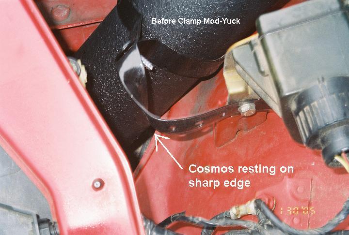
4) Remove the intake system from the filter all the way back to the throttle body.

5) Remove the alternator-cooling duct.

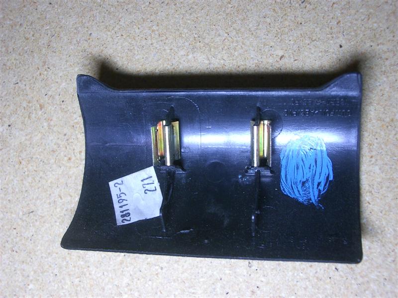
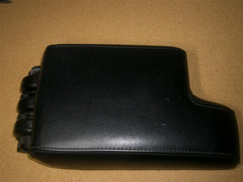
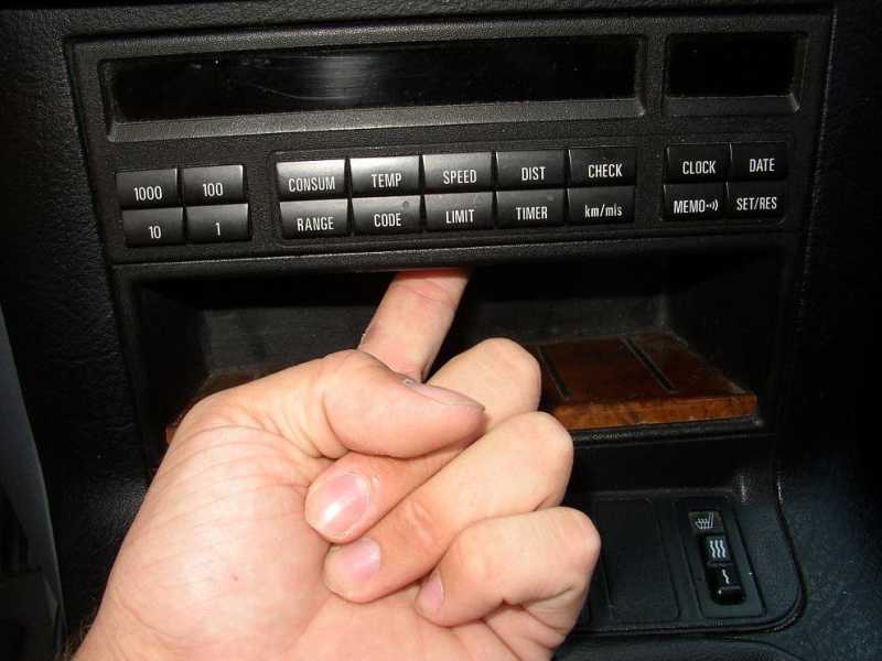
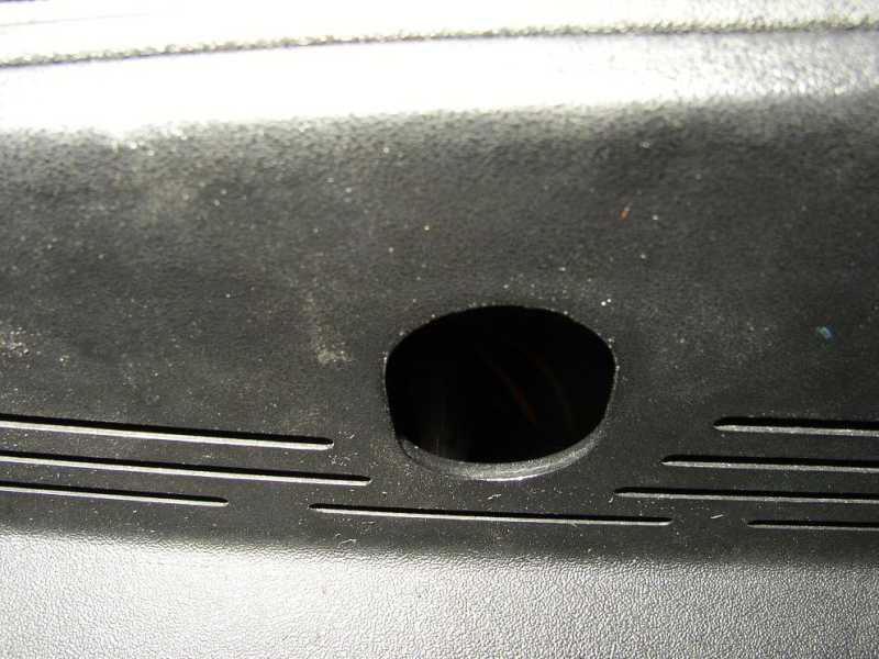
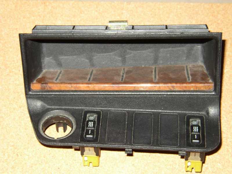
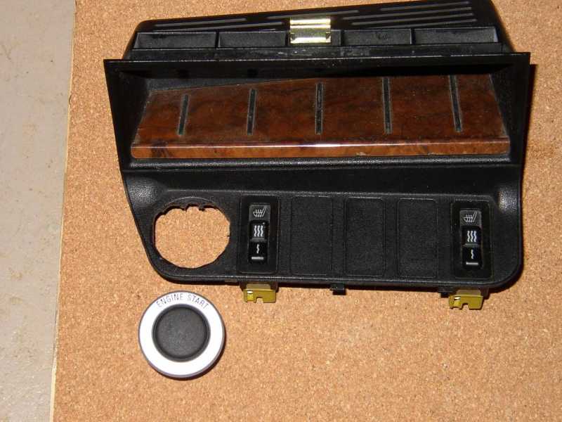
6) Remove the cosmetic plastic covers for the valve cover and fuel-injection harness.

7) If you’re replacing the fuel filter (on early build cars), this is a good time to do it. Get to the top filter clamp from above the car, and the lower one from below. Be prepared for a significant amount of fuel spillage with a catch-tray, but once the filter drains, the flow will stop. After the new filter is in, you can put the car back on the ground, but I left mine up on ramps because I found it useful to look at things from "underneath" at times, and to make collecting the dropped fasteners a little easier. I found it easier to replace the fuel filter on my early build (8/94) AFTER I had the manifold off.

8) The next few steps (9-13) are all required so you can get to the rear most manifold nut, which is obscured by the fuel rail, the pressure regulator, and the wire harness box at the firewall. It is my understanding that some cars can access this nut without doing all this, so you may want to check before proceeding. I think Roger's suggestion to do all of this is absolutely right and is the difference in making the job workable. This greatly improves access.

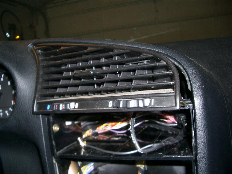
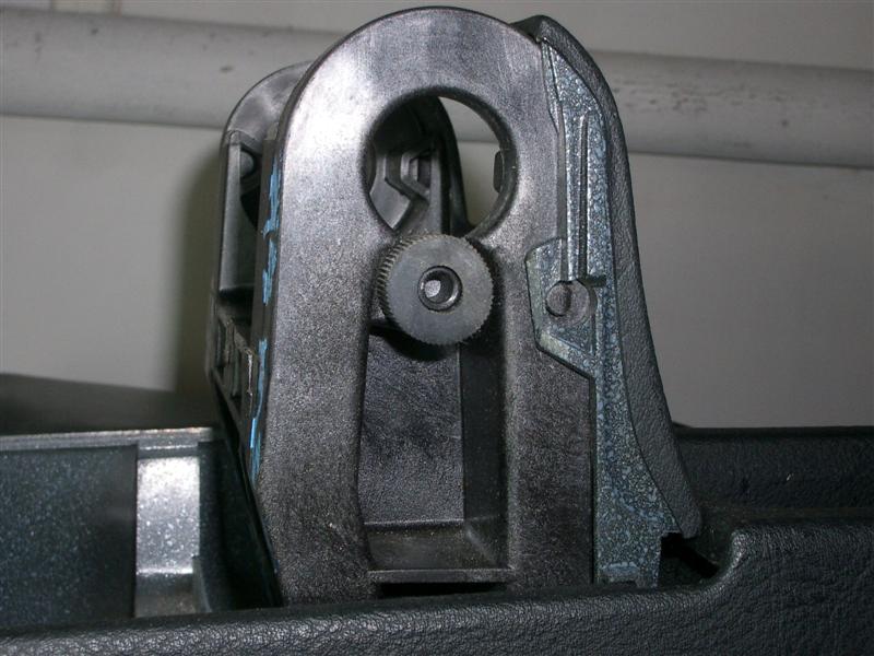
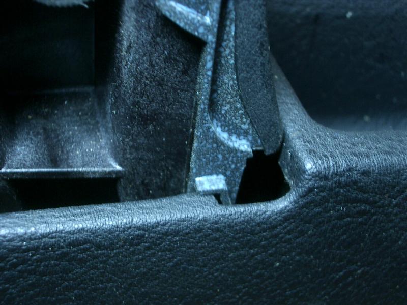
9) Remove the windshield wiper arms. On my car, this was easier said than done. The arms are pressed onto a spline and are a tight fit. You need to wiggle them while pulling them off. Mine were on so tight, I ended up using a puller, but you might get by with a screwdriver to pry them off.

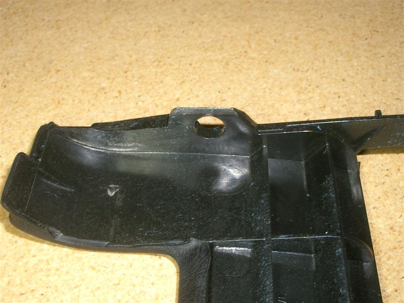
10) Remove the plastic cowling beneath the wipers. You don't have to remove it completely. I just removed the little screws holding down and lifted it up as needed. It is a pain to replace in the corners if you remove it all the way.

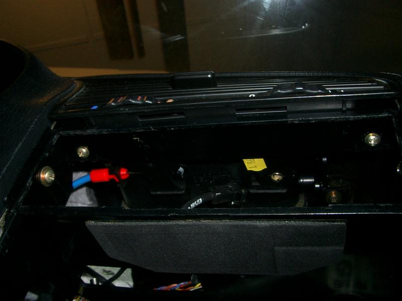
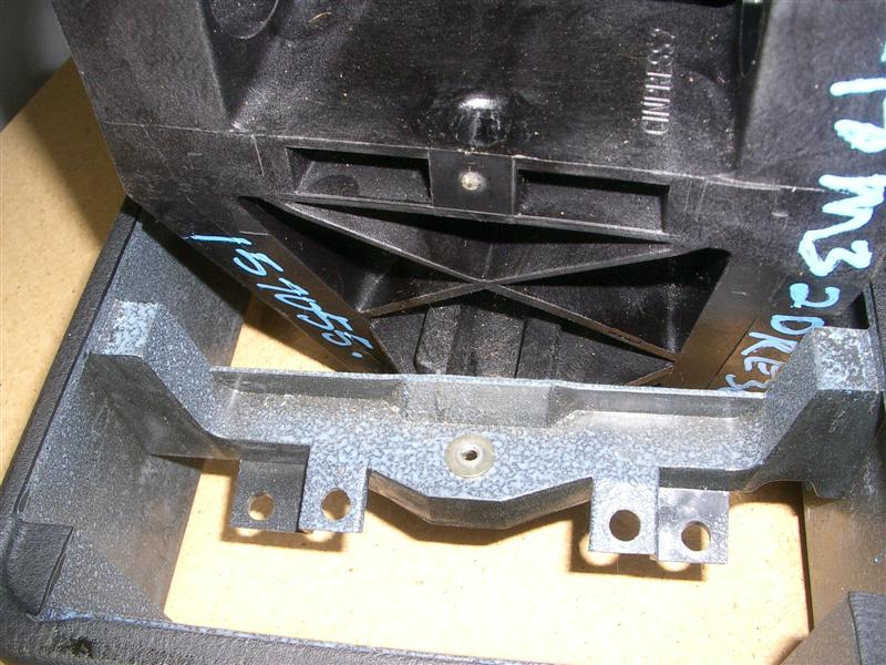
11) Remove the DME from it’s compartment in the firewall and separate it from the wire harness connector.

12) Unscrew the harness box from the lower cowling underneath the wipers.

13) Remove the lower cowling (2 screws on passenger side, one on the drivers). Essential for easing the work in the rear of the manifold.

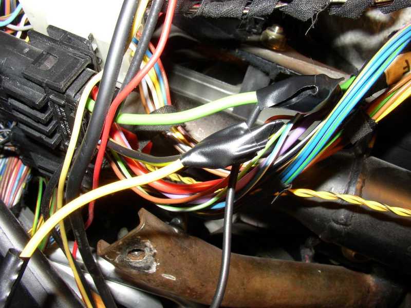
14) Cut the wire-tie above the brake booster, and pull the wire harness as far up off the manifold has possible to gain clearance with the rear most manifold nut. Temporarily secure the harness in this position with a tie-wrap or string.

15) Disconnect the electrical connector at the throttle body and unbolt the throttle body from the manifold. Leave the all the hoses attached to the throttle body.

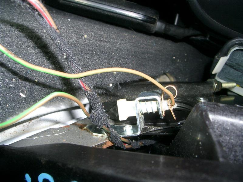
16) Using the inspection mirror, look under the manifold at the Idle Control Valve vacuum hose attachment to the manifold. It is held in place with a finger-clip type latch. You press up on this latch while pulling the large hose out of the manifold, but, again, it is easier said than done. I needed to put a small flat- head screwdriver in the latch to help coax it out. This was impossible for me to remove so I removed everything else, pulled the BACK end of this hose off the ICV, then took the manifold off, flipped it over and removed this as the last connection.

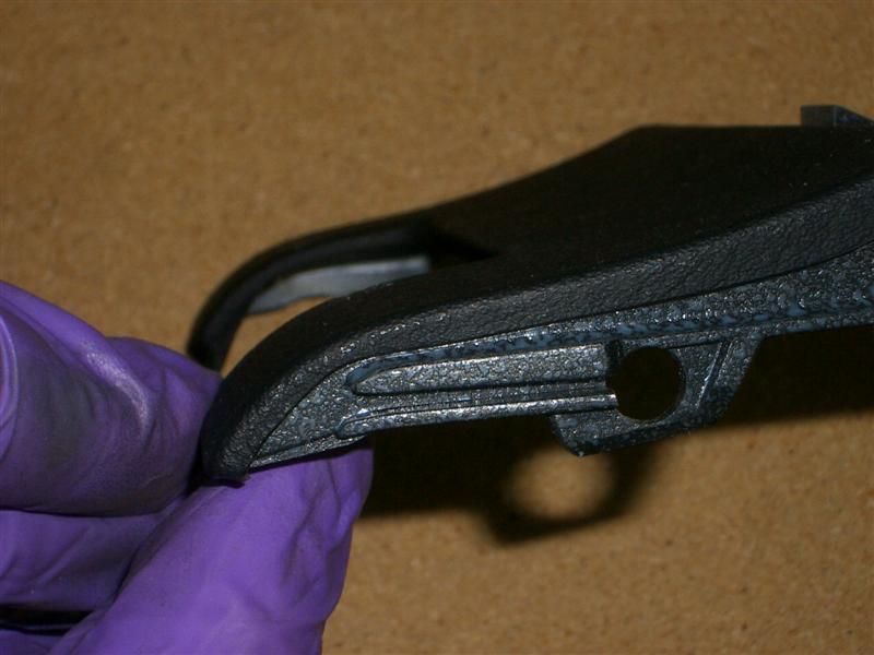
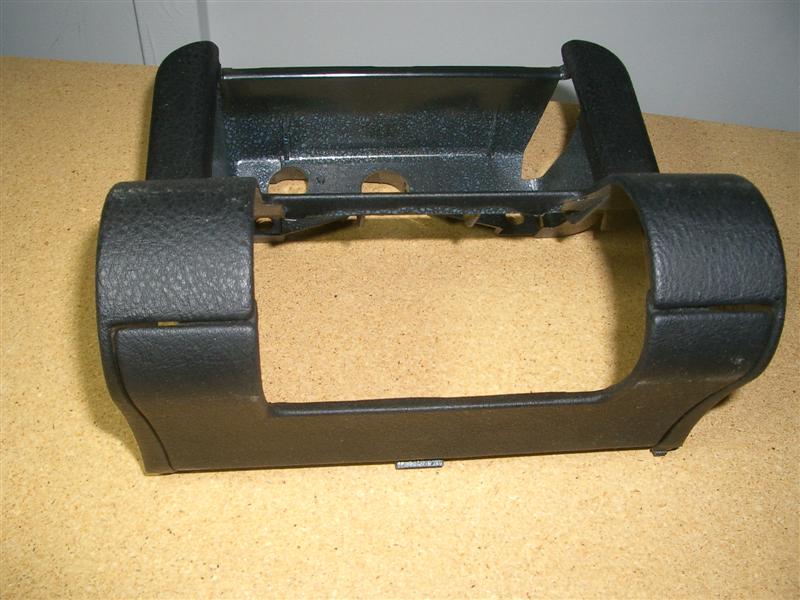
17) Remove the front and back side manifold support brackets. I removed the bolts that connect the brackets to the manifold. The rearmost one has another bracket sandwiched in with it than holds fuel lines.

18) Remove the fuel line from the front side of the fuel rail. Note that this is secured with a one-time clamp, like the other fuel line clamps, so you’ll need to use new ones for the install.

19) Remove the brake booster vacuum line at the manifold. Again, you will need a new clamp. Mine just pulled off and pushed back on. No need to replace or diddle with the clamp.

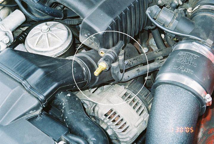
20) Remove the vacuum line at the fuel pressure regulator (no tools required, just pull it off). I had to replace this hose. It was old and hard and rotten. A real pain.

21) Remove the wire that runs to the fuel injection harness from the Vanos securing bolt.

22) Remove the nuts securing the wire harness box and fuel injection rail to the manifold.

23) Remove the restraining clips that anchor the coil wires to the valve cover to gain a little freedom of movement in the fuel injection harness.

24) Next, you need to remove the fuel rail/harness/injectors from the manifold as an assembly (they stay together as a unit). However, you will note that you have not yet removed the rear fuel line at the fuel rail. This is because the rubber hose is so short that it lacks the flexibility to pull off the rail with the fuel rail in place. So, as you remove the rail/harness/injectors from the manifold, you will simultaneously pull the fuel line off the rear of the rail. Work slowly, and remove the rail/harness/injectors off the manifold by pulling upward. Set the assembly back over the valve cover as far as it will go and secure with temporary cable-ties. This is a bit tricky - the injectors are plastic and fragile (and $70-80 each!). You need to be gentle in removing and reinstalling and even in how you sit it aside. I did tie it off, but I placed it on a towel. This is another area where taking the lower cowl out makes a big difference in freedom of movement. Some people take 1 or 2 injectors out to help. I left them all in.

25) Unclip the hard fuel line from the front underside of the manifold.

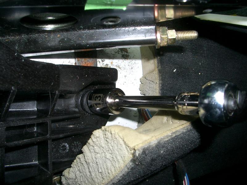
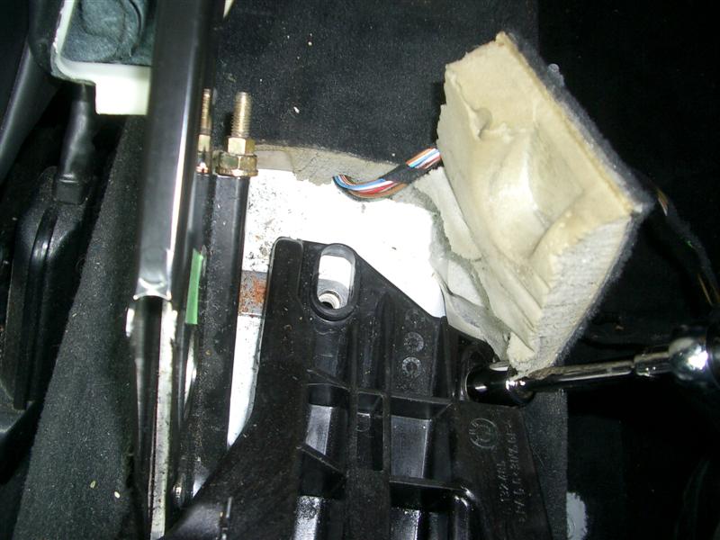
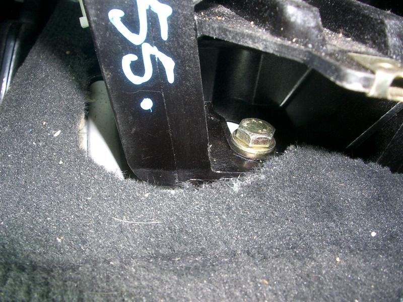
26) Unscrew the retaining nuts on the manifold. These are 11mm nuts and access to the 7th in the rear is made feasible by removing the lower cowl.

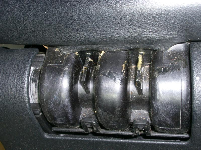
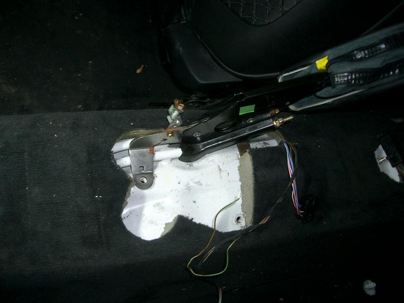
27) Pull the manifold from the cylinder head. Before you do this, blow the grit and dust off to keep particles from falling in your intake ports. As you begin pulling it off, reach under the manifold and disconnect the electrical connector from the Intake Air Temp sensor. The intake manifold should now be in your hands. The only thing dangling from it should be the vacuum line to the pressure regulator. Removing the manifold requires even pulls across the whole length of it. It takes patience.

28) Take this opportunity to inspect your intake valves. Mine had no significant carbon deposits! Gotta love Mobil gas with regular shots of Techron! Cover the intake openings with clean shop towels to prevent crap from getting in there while open.

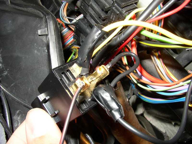
28a) Significant addition: In my car, I could see the knock sensor heads, but not the connectors. I had to remove the ICV to expose the connector portions (and even then it took some time to figure out which connectors belonged the knock sensors.) So - remove the ICV. A good time to clean it out and get rid of that erratic idle that 95 M3's seemed to have. (at least mine did). I also replaced my fuel filter at this time.

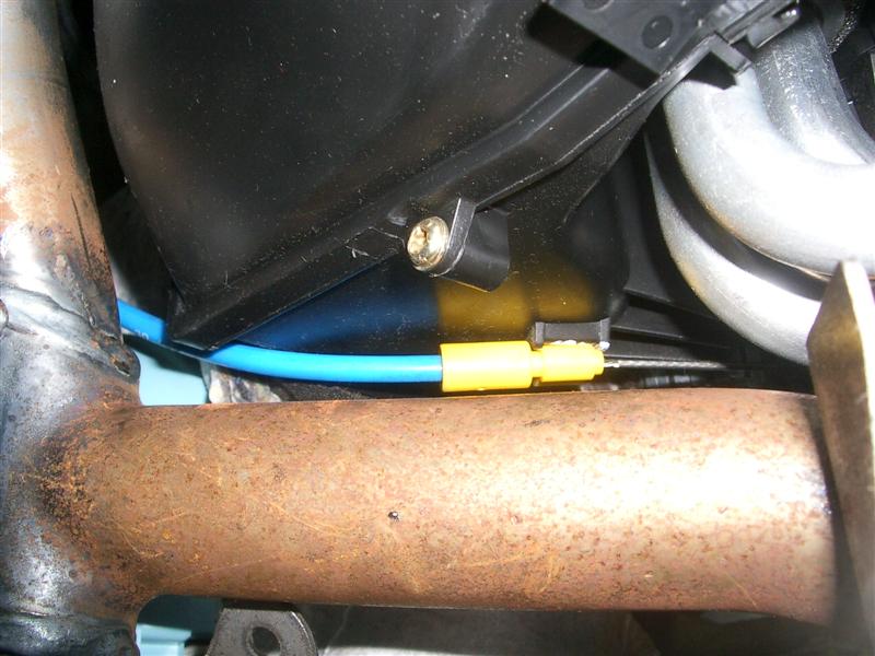
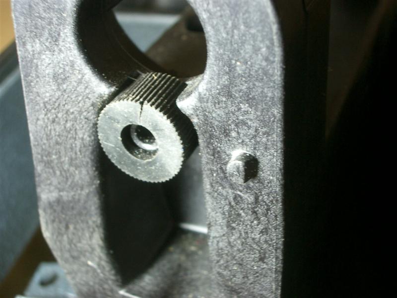
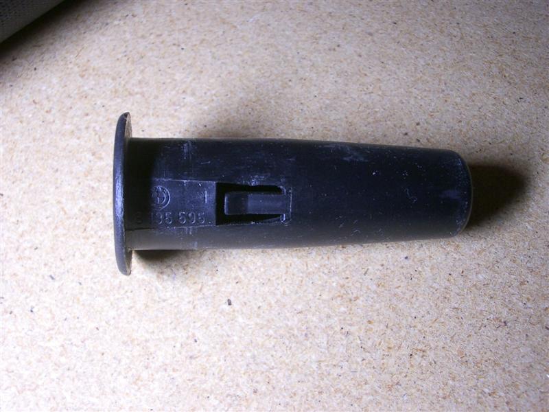
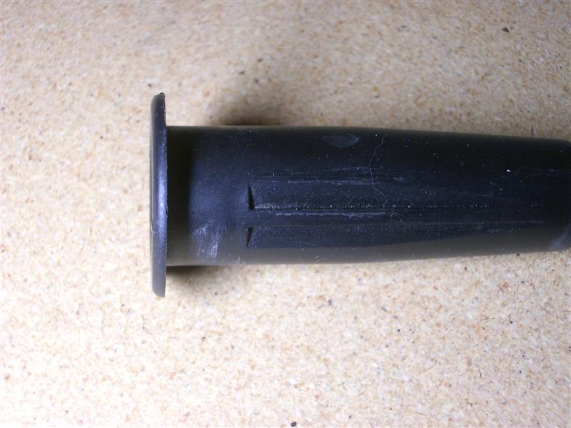
29) Remove the Number 1 knock sensor and wire connector,
noting the orientation of the sensor on the mounting boss. Clean the mounting surface, and replace with a new sensor. Use a torque wrench and torque to 15 ft-lb. You have to feed the sensor connector behind some other stuff to get it in place.

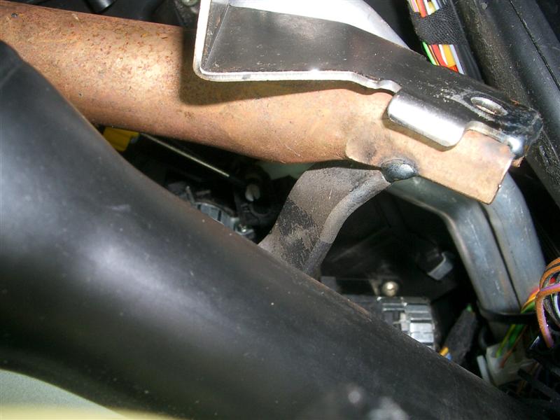
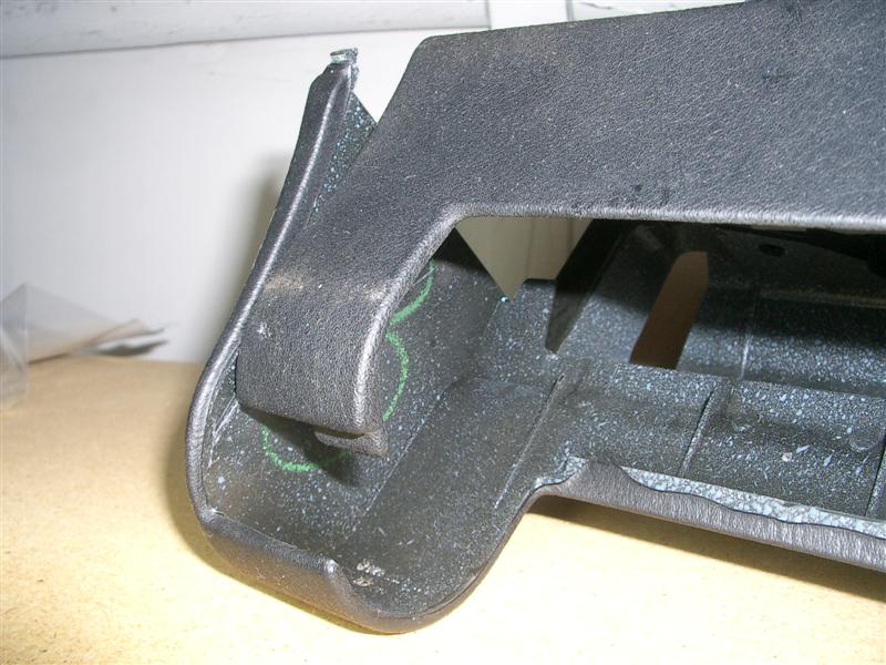
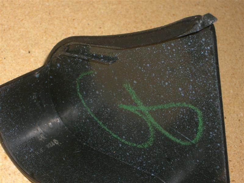
30) To get to the Number 2 sensor, you need to remove a bracket that sits over it. Once that is done, replace the sensor like you did on Number 1.

31) Replace the intake manifold and throttle-body gaskets and lube with petroleum jelly. Lube the fuel injectors o-rings, as well as any vacuum line fittings with rubber-type sealing rings.

32) Reassemble reversing the steps above. The biggest headache that I had on reassembly was rebolting the brackets to the bottom of the manifold. Two things helped: 1) don't tighten the manifold to the engine completely - allow some give. 2) loosen (but don't remove!) the lower mounting bolt on the bracket (esp rear) to allow some extra given while you blindly line it up with the hole on the manifold.

33) Let the fuel pump run a while before starting the car. Use this opportunity to reset any stored codes with your Peake Reset tool. If you don’t have one, I believe the stored codes will clear after 10 starts (assuming no additional faults). It may take several attempts to get the car to start. When it does, the idle may be erratic, but it will soon settle down and be smooth once the DME adapts. It took 3 tries to start, but when it did it ran very smoothly.

34) That’s it! Enjoy life without those annoying CE light flashes! Agreed!! Could not have done it without these instructions. Thanks RogRacer!!!!!!

BMW E36 Start Button

BMW E36 Start Button

Introduction
It has been a dream of mine since getting my car to install a Z8 start button in it just to give my car that little difference from most other E36 3's you'll see on the road or on the forums. This mod wasn't to hard to do and was relatively cheap even going with BMW Parts. It cost me about 90 bucks total after buying the parts I needed and things such as wire, relay, solder, etc.
Materials
1. One Momentary Start Button - ( I used a Z8 Start Button from Pacific BMW p/n 61 31 8 377 343 Z8 )

2. Two Contact Pins/Wires - ( Again I purchased from Pacific BMW p/n 61 13 0 006 665 )


3. One 30A/12 V Relay - ( Can be purchased at any local car parts store such as Autozone or Advance Auto Parts)

4. One Roll of Electrical Tape

5. Spool of 14-16 guage wire

Tools Required
1. Wire Stripper/Crimper

2. Wire Taps - (Optional, can use electrical tape also)

3. Wire Cutters

4. Wire Ties


5. Soldering Iron

6. Dremel w/ Grinding Stone

Getting Started
Step 1: First thing your going to need to do is remove your OBC and Console to remove the cigarette lighter so you can modify the hole to fit your new start button. To do this use your finger and pull the OBC out through the hole in sunglass holder. You may disconnect it if you would like, it will not retain its memory though. The first picture shows where to put your finger to find the hole to reach through to the OBC, the second picture is the actual hole, just feel for it you'll have no problems im sure.


Step 2: Next you want to pull out your console, be careful when pulling this out, it should just pop out but there will be some wires you'll need to disconnect: cigarette power, heated seats, and a light bulb. Once this is out pop the cigarette lighter out from the console. Push up on it from the bottom, will take a little bit of force but it will pop right out.


Step 3: Now to the dremel. Use the dremel with some type of grinding stone to make the hole a good size for your start button. I made the mistake of using a carbite cutter, just go with a good grinding stone, it will be much easier and look much better, notice how mine isn't a perfect circle. Not to worry though if you make a little bit of a mistake, the start button will cover it up and you won't be able to tell at all. Once you think you have the correct size put the start button in to test for a good fit.

Step 4: Now to the fun stuff. Your going to be spending a lot of time under your steering column so what I recommend to do is remove your driver seat. Much easier for me since I have racing seats and past experience with it but it really made it so much easier to do to be able to lay down in the car and have plenty of work space. Now is time to remove the driver side lower dash panel. There are three screws, one to the left and right of the steering wheel, and one closer to the gas pedal.

Step 5: Next step is to remove the the metal panel that is protecting all the wiring. There are 3 bolts you'll need to remove.
Step 6: Now its time to break out the nifty relay you bought. Below is a wiring diagram for the relay. I soldered a few of the connections to ensure good quality, others had to be done with electrical tape just because I wasn't about to try doing some soldering with my face under the relay and in the midst of about 1000 wires. The wires I soldered on were done in the house before I installed the relay in the car, they are noted on the diagram.


Step 7: Here goes nothing, time to make the first cut. Find the green wire and give it a cut, in the middle so you have some slack on both sides. With a piece of wire about 4" long tap it into the green wire and tape all ends together. With your piece of wire you tapped into the green wire connect it to the relay as shown on the wiring diagram (see above). Below is a picture of the ignition harness, this is where the wires you are tapping terminate. Your going to want to cut them down towards the harness that goes towards the starter as shown in the second picture.


Step 8: Next is to cut the Yellow/Black wire. (NOTE - Some cars may have a Green/Black wire instead of Yellow/Black, there is no difference in the cars, just different productions of the E36 3 series) Now is decision time, if you want your car to start with only the button ( which is what I did ) tape off the end of the wire that goes towards the ignition. If you want your car to start with either the key or the button use the same tap as you did in the previous step. Tap another 4" wire to the side of the Yellow/Black wire that goes towards the starter. Connect it to the relay as shown in the wiring diagram (see above).

Step 9: Here is just a picture of the relay used with the wires connected to it


Step 10: Now run the contact pin from the relay to up to where the start button will be located. ( If your using the Z8 Start Button connect the contact pin to pin number 1 ) Your other contact pin just needs to be ground. So find a good place to ground it and connect this pin to pin number 4 on the start button
Step 11: Now go ahead and put your key in and turn it to the on position and press your start button. If it doesn't work right away ( which mine didn't ) check your ground to make sure it has a good ground and from there check your wire taps.
Step 12: Go ahead and throw everything back together, wire tie any wires that are loose, and now and marvel at the good job you did. Feel free to show it off to everybody, lots of people will be impressed

Conclusion
This really wasn't that hard of a modification to do. I had no real experience dealing with this kind of wiring and I had no problem doing this. Have fun, pay attention to what you are cutting and pay attention to detail to make sure you have the best looking start button. Feel free to contact me at colinnicol@gmail.com if you have any questions.